With the Critical Force Test, you can determine your available maximum strength, your long-term muscular endurance and the energy storage in your forearms. Today Philipp Bulling will show you how you can set up your own test station for less than 100 euros and thus optimize your training.
Philipp Bulling has a doctorate in digital signal processing and is a passionate climber. While looking for ways to optimize his training, he came across the Critical Force Test. On Lacrux he has the concept behind it already described in detail.
As an inveterate inventor, he insisted on building his own test station and writing the necessary software for it. Philipp Bulling makes his building instructions available to all interested parties free of charge below.

You will learn that in this article
- Critical Force Test setup overview
- Hardware components required
- Required software
- Here's how it works: step-by-step instructions
Critical Force Test setup overview
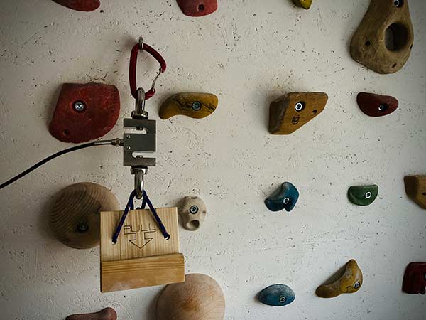
With the help of a free-hanging 20mm bar and a standard load cell, you can set up the corresponding hardware yourself with little effort. Appropriate load cells and the required amplifiers and analog/digital converters can be obtained for mid double-digit euro amounts.
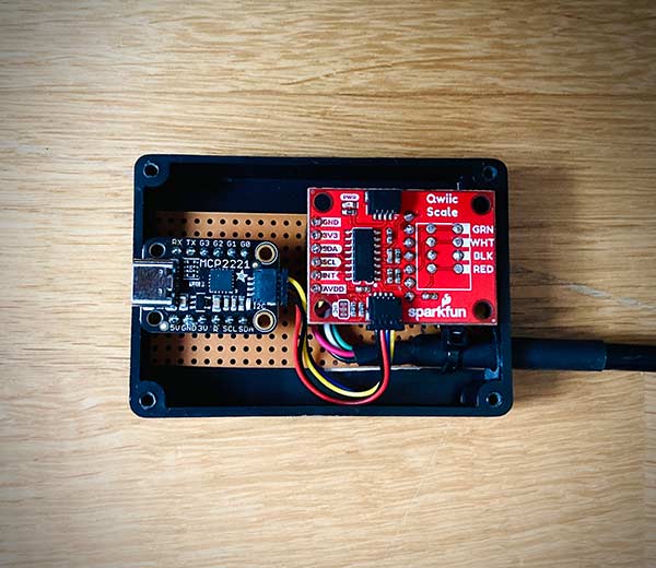
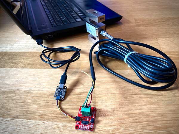
The following images show the connected hardware with which the load cell is connected to the computer via USB-C. Software for evaluating the parameters is provided by the author as part of an open source project. More on this in the chapter Required software.

Hardware components required
To build your personal Critical Force test station, you need the following hardware components. The linked products are not affiliate links, but only a possible suggestion of where they can be purchased.
| Articles | Comment | Quantity | Price |
| wooden strip | Preferably 20mm or 10mm wide to ensure comparability | ||
| load cell | Or comparable (approx. 100 kg) | 1 | 40.29 Euros |
| load cell module | Manufacturer Sparkfun | 1 | 19.65 Euros |
| USB Interface | Manufacturer Adafruit | 1 | 7.75 Euros |
| Cables | For connecting USB interface/load cell module | 1 | 1.15 Euros |
| USB-C cable | For connection to computer | 1 | 2.10 Euros |
| Eyebolt M12 | Thread diameter must match the load cell | 2 | 14.90 Euros |
Required software
The software you need to evaluate the measured parameters was written by Philipp Bulling as part of an open source project. He puts them on his Blog available free of charge.
Be sure to calibrate the load cell before using it for the first time. To do this, go to Settings/Calibration and follow the instructions. Anyone wishing to contribute to the source code will find all the information they need here GitHub.
Here's how it works: step-by-step instructions
First, the load cell is connected to the amplifier module (NAU7802). Most commercially available load cells are equipped with a four or five-wire cable for this purpose. The cables colored red, green, white and black are connected to the correspondingly labeled inputs of the amplifier module.
The fifth cable (yellow) can optionally be soldered if there are problems with the signal transmission. Normally, however, it is not required. The amplifier is then connected to the USB module (MCP2221) using the Qwiic cable. It doesn't matter which of the two sockets on the amplifier is used. Finally, the USB module can be connected to the computer with a USB-C cable.

The driver for the USB module will then be installed automatically. Once this is complete, the software can be launched. It must be ensured that the load cell is checked each time the software is started and that all weights must therefore be removed from the load cell during the start.
For correct commissioning, the load cell must be calibrated once. The calibration can be started from the software via «Settings/Calibration». To do this, two different known weights must be attached to the load cell and the weight noted in the corresponding dialog box. After restarting the software, the calibration is applied and the tool is ready for use.

